General Operating Instructions
Adjustment of Measurement Range and Zero Point
The modules with a fixed measurement range are precisely calibrated at the factory (error usually less than 0.05%), further calibration is generally unnecessary. If the output values are not correct, first of all check the connections, the power supply (is the supply voltage correct ?) the experimental arrangement and all instruments in use.
We recommend that when working with programmable or configurable modules, the calibration should be checked after each new adjustment.
Adjustment is performed using a calibrator or a calibrated sensing device. The zero point is adjusted via the "Offs" potentiometer and the final value adjusted via the "gain" potentiometer. The zero point is adjusted first and then the final value. Where large adjustments are necessary, the procedure should be carried out several times. For additional reliability, the output value should be measured at half the measurement range (linearity test).
In some modules which have a monopolar supply voltage, the output voltage never quite reaches 0 mV. In such cases, zero point adjustment must be performed with an input value which produces a non-zero output value.
Please also observe the tips and information to be found in the operating instructions for the individual measurement transducers.
Supply voltage connection for a printed circuit board module
 |
For units with a bi-polar supply, the negative voltage should be connected to pin 1. If the supply voltage is not filtered (i.e., direct from a DC-DC converter), the use of a 50 Ohm series resistor is recommended. If the module will be subject to HF interference, the use of an output filter (e.g., 50 Ohm/470 nF) is recommended. This is not necessary if the receiver is equipped with adequate filters. |
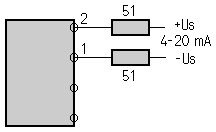
Supply voltage connection for a 4-20 mA printed circuit board module
 |
For a non-filtered supply (i.e., direct from a DC-DC converter), the use of a 50 Ohm series resistor is to be recommended. |
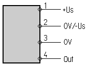
Supply voltage connection for a DIN rail module
 |
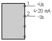
For units with a mono-polar supply voltage, this should be connected to terminals 1 and 2 (1: +Us, 2: 0 V). Terminals 2 and 3 (0 V) are connected internally for mono-polar supplies. For EMC reasons, we recommend that the input is connected across terminals 1 and 2 and the output voltage (or output current) taken between terminals 3 and 4. For units with a bi-polar supply voltage, the negative voltage should be connected to terminal 2 and the supply earth and signal ground should be connected to terminal 3. |
Supply voltage connection for a 4-20 mA DIN rail module

Connection of one 4-20 mA module

The resistor RL converts the current (4-20 mA) to a voltage signal, U. Where HF interference can not be discounted, it is recommended that a filter (CF and RF) be installed in front of the shunt resistor (RL). RF is typically approx. 100 Ohm and CF 100 nF up to several mF. Such a filter is generally required (usually together with an overvoltage arrester, e.g., a ZNR) in order to fulfil EC-EMC standards.
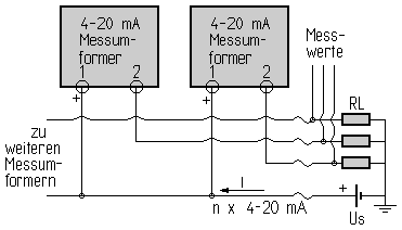
Connection of several 4-20 mA modules

Many 4-20 mA modules can easily be supplied from a single source. Each measurement transducer requires a separate shunt resistor (RL). Use of an HF filter and overvoltage arrester is recommended (see connection of one 4-20 mA module).