
- Details
- Written by Soclair Electronic AG
- Category: Uncategorised
- Hits: 2297
Digital Frequency-Voltage Transducer, FVM 70/82
General Description
These transducers convert a frequency signal of any form and polarity into a normalised voltage or current signal (e.g., 0-10 V or 4-20 mA). The measurement range is selected via DIL-switches on the back of the unit. The standard version has 64 calibrated ranges from 0-100 Hz to 0-28.8 kHz.
Special versions are available for low frequencies (FVM70/82 – L). The measuring range can be selected via DIL-switches in steps of 0.1 Hz between 0-0.1 Hz and 0-12.7 Hz or in steps of 1 Hz between 0-1 Hz and 0-127 Hz. The analog output signal is completely ripple-free.
Version FVM70/82-2L allows the adjustment of the measuring range in steps of 10 Hz between 0-10 Hz and 0-1270 Hz. The analog output signal is completely ripple-free.
- For flow measurement and other frequency signals
- Digital frequency to voltage conversion, extremely accurate
- Schmitt-trigger input protects against interference, AC-coupling
- Low frequency versions, ranges down to 0-0.1 Hz, ripple-free output signal
- Control LED on units with 24 V power supply
- Different housings available
Overview
Modules for DIN-Rails |
|||
| Type | Output | Power Supply | Range |
|---|---|---|---|
| FVM 70 | V | 21-30V/±15V | progr. |
| FVM 82 | 0/4-20mA | 21-30V | progr. |
Printed Circuit Board/Euro-Card Modules |
|||
| Type | Output | Power Supply | Range |
|---|---|---|---|
| SIGF 10 | V | 14-30V/±15V | progr. |
| SIGF 32 | 0/4-20mA | 17-30V | progr. |
Output
- Voltage output (e.g., 0-10 V): typ. 50 Ohm output impedance, max. 5mA.
- Current output (0/4-20 mA): 300 Ohm max. load, when ordering please indicate if 0-20 mA or 4-20 mA.
Power Supply
- Requires a bipolar power supply (e.g., ±15 V) for a negative output voltage. Units with a unipolar supply (standard version) have a min. output voltage of ca. 20 mV. Current requirement with no load ca. 10 mA.
Range
- 64 calibrated ranges (error < 0.1%) between 0-100 Hz and 0-28,800 Hz can be selected via DIL-switches on the back of the unit (intermediate values set by a potentiometer).
When ordering, please specify
- module type
- accuracy class (A, C, or D)
- input range (in Hz)
- output range (in mA or V)
- supply voltage (in V, uni- or bipolar)
- Only the module type and accuracy class (A or C) has to be specified for programmable versions
Operating Instructions
Range Setting Table
|
|
||||||||||||||||||||||||||||||||||||||||||||||||||||||||||||||||||||||||||||||||||||||||||||||||||||||||||||||||||||||||||||||||||||||||||||||||||||||||||||||||||||||||||||||||||||||||||||||||||||||||||||||||||||||||||||||||||||||||||||||||||||||||||||||||||||||||||||||||||||||||||||||||||||||||||||||||||||||||||||||||||||||||||||||||||||||||||||||||||||||||||||||||||||||||||||||||||||||||||||||||||||||||||||||||||||||||||||||||||||||||||||||||||||||||||||||||||||||||||||
Other output voltages and currents: In the standard module, the output is 0-10 V, 0-20 mA or 4-20 mA. If a different output range is required, e.g., 0-1 kHz = 0-2 V, one must calculate the corresponding measurement range for 0-10 V, i.e., in the above example 0-5 kHz = 0-10 V. When this range is selected one automatically obtains 0-1 kHz = 0-2 V. The rule is: always convert first to 0-10 V (or 0-20 mA or 4-20 mA).
Detailed Data Sheet
- Details
- Written by Soclair Electronic AG
- Category: Uncategorised
- Hits: 8806
Housings
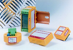
DIN-Rail Modules
 |
These modules are supplied with screw terminal connectors and two potentiometers (for gain and offset adjustment, each with an adjustment range between 3 and 10%, depending on the module). The modules are precision calibrated in the factory. |
Size: 55 x 60 x 23 mm (2.17 x 2.36 x 0.91 inches)
All connections have filters/overvoltage arresters (to 4 kV) for very hostile industrial environments. Most of the transducers are available in two versions: with a specific, fixed, customer-specific range (provides a low-cost solution for large volumes) or a programmable range (for smaller numbers of pieces and/or for optimization of stock-keeping/logistic/flexibility).
Options
- Built-in DC-DC converter for galvanic isolation of the 24 V supply.
- Built-in adjustable limiting switch for monitoring and control, contains a relay switcher (finger connectors on the side of the module), potentiometer adjusts the switching treshold. A detailed data sheet is available.
- Very narrow enclosure (not available for all types): 55 x 60 x 12 mm (2.17 x 2.36 x 0.47 inches).
Printed Circuit Board/Euro-Card Modules (E4K1, EMUX1)
 |
These modules have pins (0.7 x 0.7 mm (0.028 inches), drill diameter 1.0 mm (0.039 inches) min.) for soldering the module horizontally or vertically onto the circuit board. Two external potentiometers are required (1 kOhm each as standard, SCM/FVM: 10 kOhm) for gain and offset adjustment. Most modules are available in two versions: fixed or programmable range. |
Size: 55 x 32 x 15 mm (2.17 x 1.26 x 0.59 inches)
All connectors have filters and are immune to voltage spikes up to 1 kV (IEC 801-5).
Accessories
- Euro-card for four modules (E4K1)
- Euro-card with 6-channel multiplexer for one module (EMUX1)
Modules for DIN-Heads (Type B)
 |
These transducers have screw terminal connectors and two built-in potentiometers (for gain and offset adjustment, adjustment range typ. 5%), only fixed range. These modules are precision calibrated in the factory. All connections have filters/overvoltage arresters (to 4 kV) for very hostile industrial environments. |
Diameter: 44 mm (1.73 inches); max. height: 26 mm (1.02 inches)
Printed Circuit Board Modules
| These modules have soldering pins, two built-in potentiometers (for gain and offset adjustment, adjustment range typ. 5%), they are only available with fixed range and are precision calibrated in the factory. |
Size: 20 x 30 x 15 mm (0.79 x 1.18 x 0.59 inches) or 30 x 30 x 15 mm (1.18 x 1.18 x 0.59 inches)
- Details
- Written by Soclair Electronic AG
- Category: Uncategorised
- Hits: 8032
EMC Tests using High Voltage Spark Gaps
In industrial environments, spark flashover often present the most common, toughest and widest ranging interference sources. It is therefore obvious that in addition to the standard test methods (e.g., IEC/EN 61000-4) a spark test should also be carried out. The interference impulses from IEC/EN 61000-4-4 more or less simulate the spectrum of from a spark. However, the fields from IEC/EN 61000-4-3 (10 V/m, CW) are not in any way similar to spark generated fields.
Sparks result primarily from switching systems (e.g., relays, switches) and in electric motors (collector) but can also result from electrostatic and atmospheric discharges, ignition systems (combustion motors), welding equipment, etc. Interference generated in this way is extremely broad-band (up to 1 GHz). For a breakdown at atmospheric conditions, a field strength of approx. 3 million V/m is necessary. In the immediate vicinity of a spark the resulting field strength is of the order of several hundred thousand V/m.
Tests on a Measurement Transducer
The test object is a standard Pt-100 measurement transducer, type RTM 70-C, with a measurement range of 0-100°C = 0-10 V. The 0-10 V output of the module is connected to a seven-segment display which shows the ambient temperature (measured by a Pt-100 sensor) in °C (resolution 1/10°C). The high voltage sparks is applied to the sensor cables during normal operation. During the tests, the frequency of the sparks is varied between 1 and 100 Hz. No change in the display (1/10°C resolution) could be detected during any of the tests. The entire spark current (with frequency components or up to approx. 1 GHz) has to flow through the module before returning to the high voltage generator via the earth cable.
In such tests various interference mechanisms come into play:
Field related interference: The spark gap is approx. 1 cm. Separation from module, approx. 5 cm. Measurement transducers can tolerate field strengths of several ten thousand to several hundred thousand V/m. In spite of the fact that the measurement transducer is not shielded (plastic casing), it is unaffected by the interference. Variation of the order of a few mV can be detected.
Conducted interference: The Pt-100 sensor is connected to the measurement transducer via two-wire technology. The positive wire leads the measurement current through the sensor (approx. 1 mA), and at the same time the drop in voltage is measured at the module. The negative wire leads the measurement current back and serves as the zero point for the voltage measurement. The wire is connected to the module¢s analog ground. The spark is applied at the negative wire. Coupled into the neighbouring positive wire are high-voltages interference signals (direct galvanic and via the electromagnetic fields) which are completely eliminated by the over-voltage arrester at the input and by the various filter stages. At the output and the power supply connections, larger interference voltages will certainly occur, but will not affect the signal. The display (also available from SOCLAIR ELECTRONIC) has over-voltage arresters and various filters at the signal input and power supply which renders it completely immune to interference voltages. None of the wires are screened. The entire HF spark current flows through the module's ground system without causing interference of any kind.
A spark applied to the positive cable must, of course, have a noticeable effect: due to direct galvanic coupling, an interference signal which contains a DC element is superimposed on the measurement signal. The DC element cannot be eliminated by the filters. However, of critical importance is the fact that with this type of coupling, the over-voltage arrester and the filters protect the module from high voltage (approx. 30,000 V).
How much does good EMC protection cost?
It goes without saying that such extraordinary high interference security is not easy to achieve. However, assuming the relevant know-how, the cost of the product scarcely increases. Of greatest influence is the layout (the geometry of the circuit, and of the ground in particular), the grounding concept, the circuit technology and the selection of EMC-resistant components. The additional circuit elements (over-voltage arrester, filters) add no more than a few percent to the total price, assuming optimum design, and the other measures cost practically nothing. If the measurement transducer is designed properly then additions such as metal casing, screened cabling and other expensive screening elements become unnecessary.
- Details
- Written by Soclair Electronic AG
- Category: Uncategorised
- Hits: 4116
Contact Address
Soclair Electronic AG
Sonnmattstrasse 7
CH-5304 Endingen
Switzerland
This email address is being protected from spambots. You need JavaScript enabled to view it.
Please note that Soclair Electronic AG is not a sales point. Technical questions are welcome.
All commercial issues (e.g. a quote) are handled by our sales representatives/distributors.
- Details
- Written by Soclair Electronic AG
- Category: Uncategorised
- Hits: 7869
Connection Technology
2-, 3-, or 4-wire connection for resistors
When measuring resistance, particularly for Pt-100 sensors, one uses, according to accuracy requirements and economic constraints 2-, 3- or 4 wire technology. The advantages and disadvantages of the technologies are discussed below.
2-Wire Connection
The obvious advantage of 2-wire connections is their simple wiring. However, this technology can easily lead to large errors: an additional resistance of one Ohm (cable resistance, junction resistance at solder joints, connectors, etc.) can cause an error of 2.5 degrees in a Pt-100 transducer. The error acts as an offset (zero point shift) and can, in principle, be trimmed. However these resistances are not constant (due to temperature, aging), particularly in the case of junction resistances at points of contact (connectors, screw terminals) and even the cable resistance (copper) can alter by approx. 0.4%/K. These variations can lead to significant errors.
In practice, 2-wire technology is only recommended in cases where great accuracy is not required or where the connections are short with very low junction resistance (e.g., good solder joints). When mounting a module in the Type B DIN43729 head of a sensor, these requirements are usually well fulfilled.
3-Wire Connection
In a 3-wire connection, one wire (the sensor wire) measures the cable and junction resistance and with the help of a suitable electronic circuit, the influence of the additional resistances can be largely eliminated. However, this only applies under a certain condition which is often not fulfilled: the resistances of the three wires and of the junction points must be matched exactly. A difference of only 0.39 Ohms results in an error of 1 degree (Pt-100). Even in the case of exact matching (which is uneconomical) the problem of variation caused by temperature and aging exists. In this respect, the 3-wire technology is hardly better than the two wire variation. Compensation of lead resistance is usually achieved by unequal amplification (+2, -1) of the positive and negative signal inputs. Due to this asymmetry, the three wire technology is also more sensitive to interference voltages (thermo-voltages, electromagnetic interference) than the 2- or 4-wire versions.
In practice, the 3-wire connection is usually more unstable than either the 2- or 4-wire measurement. The measured offset drift in a 3-wire system can often be attributed to the thermo-voltage at the connection.
4-Wire Connection
With this type of connection, 2 wires are used to deliver and return the constant measurement current. Two additional wires (sensor wires) are used for a high ohmic measurement of the voltage drop across the resistance sensor. The influence of the wire and junction resistance is eliminated (approx. error 0.002-0.004%/Ohm). These resistances may also be different for the different cabels and may alter with time without affecting the output signal. Although this connection system requires more wiring, it is generally still the most economical since it requires no adjustment.
Connection Possibilities for RTM Modules
All Soclair Electronic Pt-100 (or resistance) modules are available for 3- or 2-/4-wire connection. Generally, the 2-wire version is realised in a 4-wire module which must be short circuited as close to the module as possible (see diagram).
In the programmable modules (e.g., RTM 90), the connection type (2-/4-wire, 3-wire) is selected via the mini switches.
In modules with fixed measurement ranges, the type of connection cannot be changed (except for 2-wire connection on a 4-wire module).
 |
Point of connection for the sensor wire (F) as close as possible to the resistor. |